Fan-Tas-Tic score reels
The 16 score reels of my electro-mechanical (EM) pinball machine are a good test for the in- and output extension boards I’ve been working on recently.
The input extension board
This is a really minimalistic board providing 8 additional digital input channels.
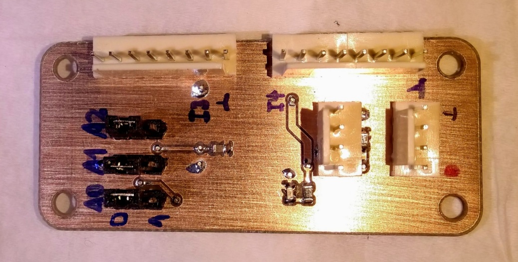
I2C and +5V come in on one of the 2 connectors on the right. The other connector
can be used for daisy-chaining the bus to another board or to attach the termination plug.
The 2 connectors at the top are for connecting the 8 switches. The jumpers on the left select the I2C address (0x20 - 0x27).
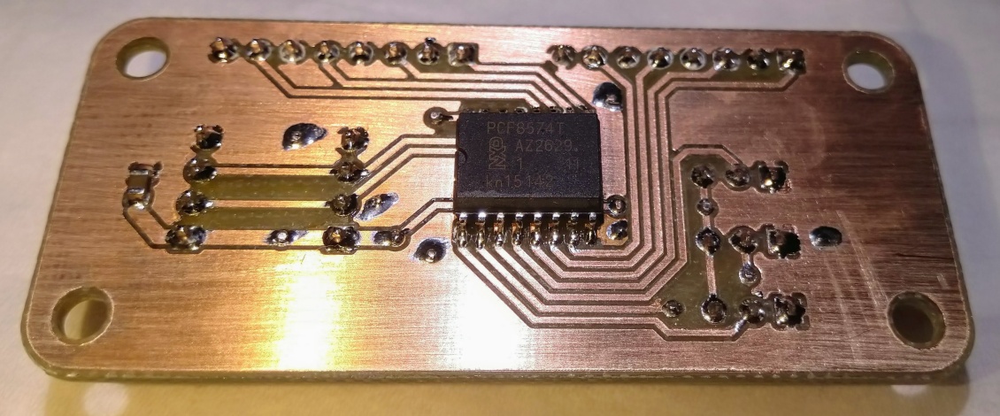
The PCF8574 IO extension chip is on the backside of the board.
The output extension board
This board provides 8 open-drain output channels. Its main goal is to drive solenoids but you can really drive anything with it, like motors, LEDs, heaters, lightbulbs …
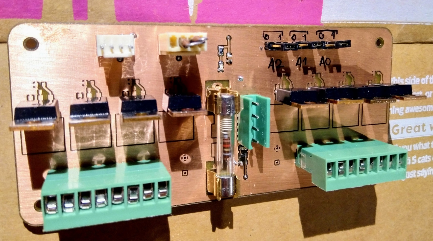
The I2C and +5V connectors are at the top. Note the termination plug on the second I2C connector. There are 8 x TO220 mosfets on this board. However there are also footprints for TO263 and SOT23 devices. So Install whatever is on hand and fits the job.
In the middle is the 24V input connector and one shared fuse for all outputs. Also there’s 2 LEDs for indicating +5V and +24V are present.
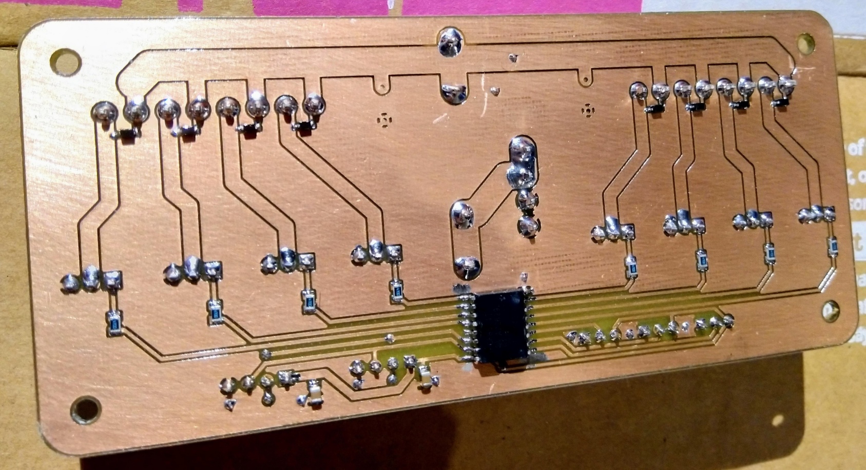
The backside shows the PCF chip. Towards the top are 8 Schottky diodes to provide a free-wheeling path for the current when switching off solenoids. I was quite optimistic with my choice of tiny SOD123 devices here and already killed 2 of them.
In the next revision of the board there will be larger footprints for the diodes and maybe even a through hole option, as there is plenty of space.
In practice
when you remove the painted glass from the head of the machine, the score reels become visible.
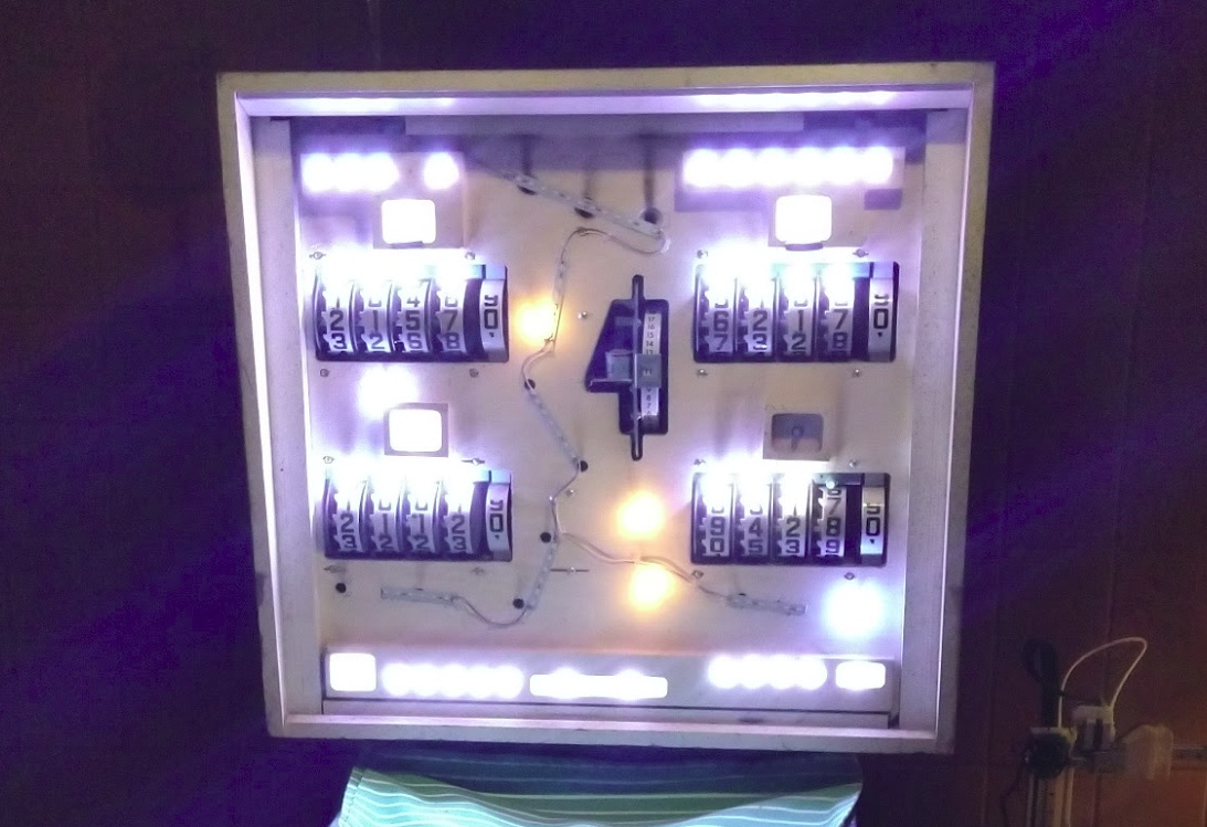
It can show the score of up to 4 players. The large wheel in the middle is the credit counter. I think it used to show how many games you can still play for the amount of money you have inserted.
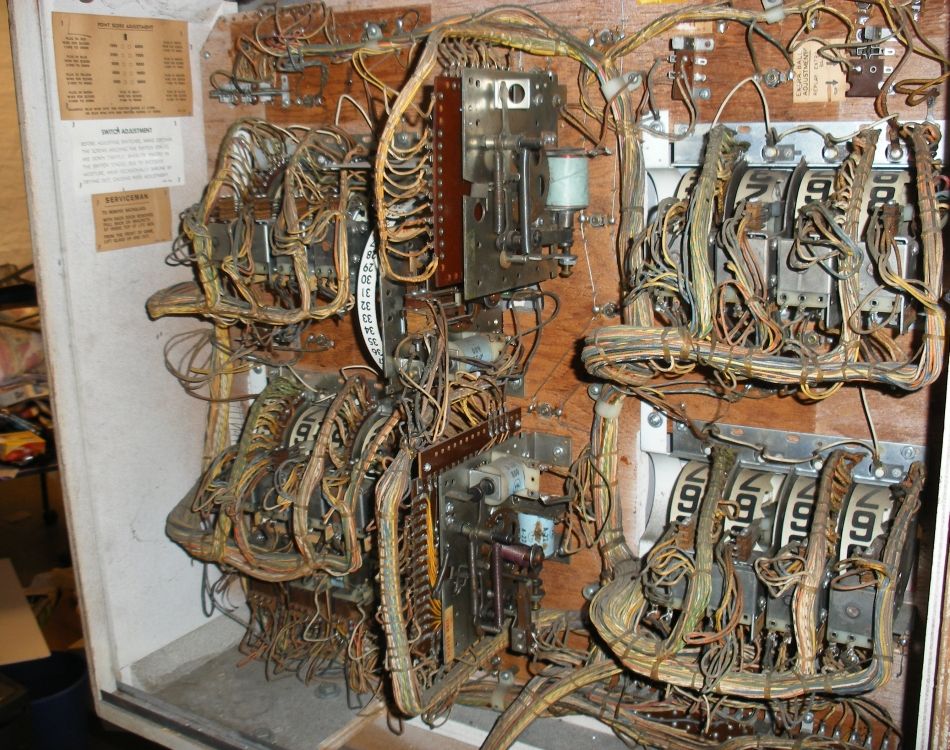
From the back, that’s how its original guts used to look like. Everything is purely electro-mechanical and driven by relays and rotating commutators.
Some things to note
- Cotton insulation on all wires. Soldering them smells like fresh laundry :D
- By plugging pins into specific sockets, configuration was possible. How many balls per play, or at which score to get an extra ball …
- Filament light bulbs poke through the wood which get pretty hot
I removed and cleaned up all of it. The lights have been replaced by a WS2811 LED string, which by chance had the same diameter and fit well in the original holes in the wood.
For the right 2 score reels I installed and wired up one in- and one output extension board.
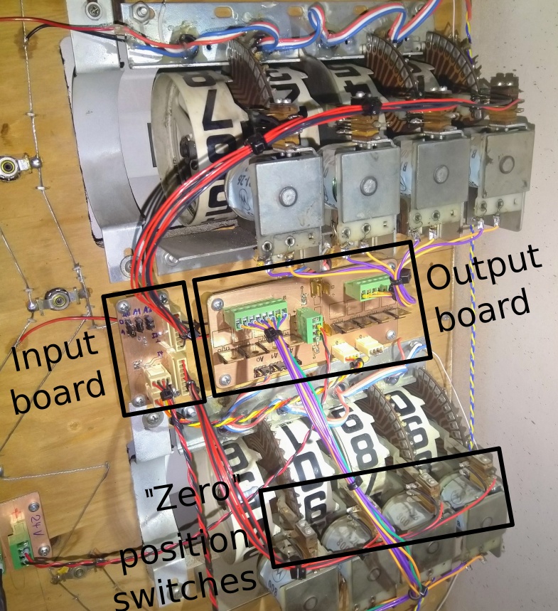
The input board reads when the reels are in zero position. The output board is driving the solenoids with 24V. To increment the count reliably, a 10 ms pulse is enough.
Software
Mission pinball fully supports score reels. Here’s the interesting parts of my config.
First define the coils and switches
switches:
    s_score_p1_1:
        number: 0x8b  # 10 counts
coils:
    c_score_p1_1:
        number: 0x83  # 10 counts
        default_pulse_ms: 10
        default_pulse_power: 1.0
Then, in true OOP fashion, combine them to get a score reel. With the
current setting for repeat_pulse_time I get up to 10 pulses per second.
Reseting the reels sounds like a machine gun!
score_reels:
    score_p1_1:
        coil_inc: c_score_p1_1
        switch_0: s_score_p1_1
        repeat_pulse_time: 100
Combine several reels to get a score counter and connect it to an actual player score
score_reel_groups:
    player1:
        reels: score_p1_4, score_p1_3, score_p1_2, score_p1_1, None
        tags: player1
        lights_tag: l_bg_p1_score
And that’s all I had to do. MPF takes care of zero-ing the reels and even notices and corrects if a step was missing.
The mechanical clicking of the wheels really adds something to the game and feels strangely satisfying.
Update 04/2019
I got all 16 channels working reliably now. One I2C channel has a chain of 2 input boards and 2 output boards connected to it. Initially I had some connection issues. Some conformal coating accidentally got on the contacts of the address-select jumpers. So one of the boards had a wrong address and took the whole bus down. After tracking down and fixing this problem everything has been working quite smoothly since.
Here’s how Mission Pinball resets the score wheels after starting a new game (Headphone warning!):