hex_lamp
The inspiration for this project came from a recent visit to the Oakland Museum. They had a temporary burning man exhibit featuring these huge, beautiful lamps made by HYBYCOZO.
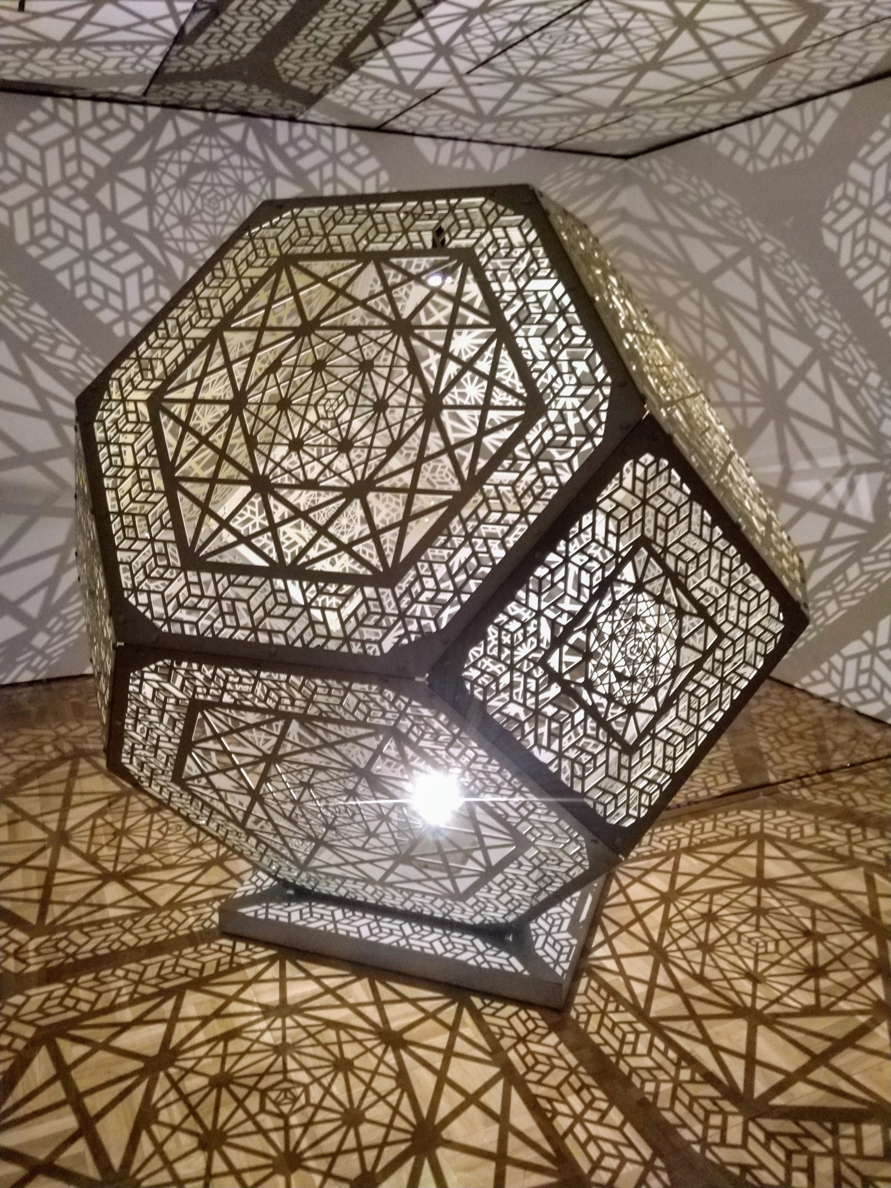
I wanted to create a similar but smaller lamp using plywood, laser-cutter, and 3D printed pieces to join everything together. I was excited to learn about the geometry, the symmetries of the artwork and how different LED lights create different shadow effects.
 Design
I found some info about the geometry on the wiki:
- truncated octahedron
- 6 square shaped pieces
- 8 hex shaped pieces of same side-length
- 24 joiner pieces
- the squares only touch hexes
- hexes alternately touch hex and square
- angle between hex - hex =
arccos(−1 / 3)= 109.471° - angle between hex - square =
arccos(−1 / sqrt(3))= 125.264°
I started modeling the shape in OpenScad to better understand how the pieces will fit together.
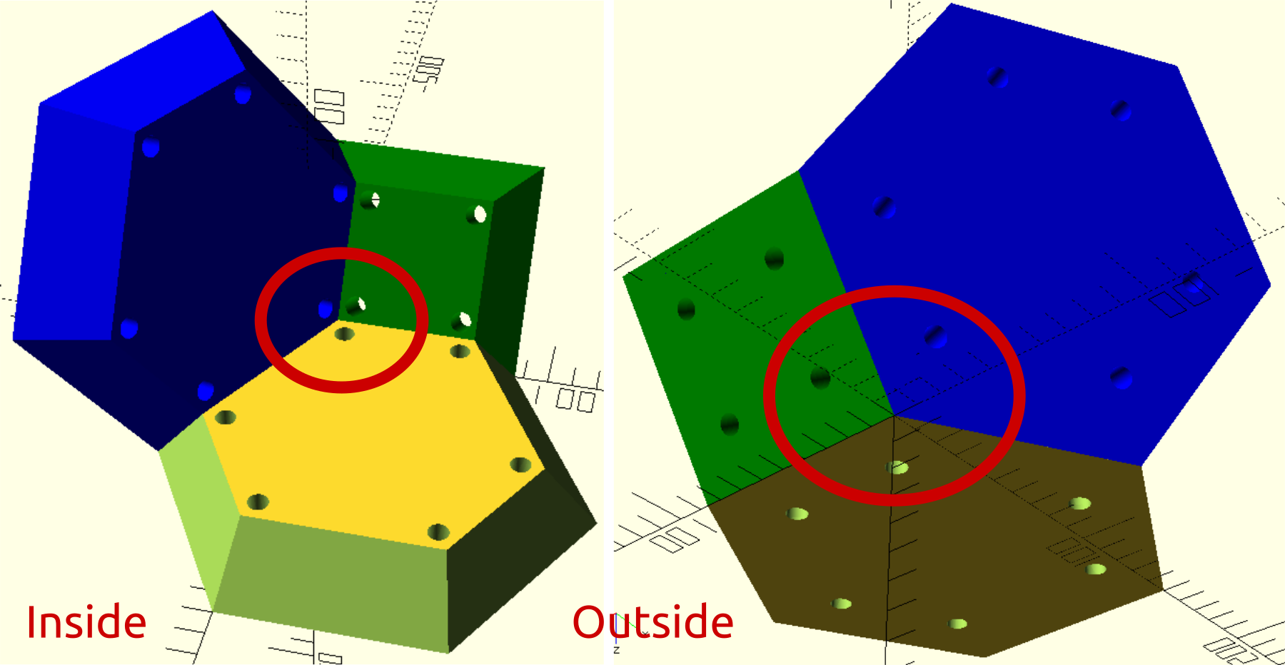
When building this from material of non-finite thickness, 2 things need to be taken into account:
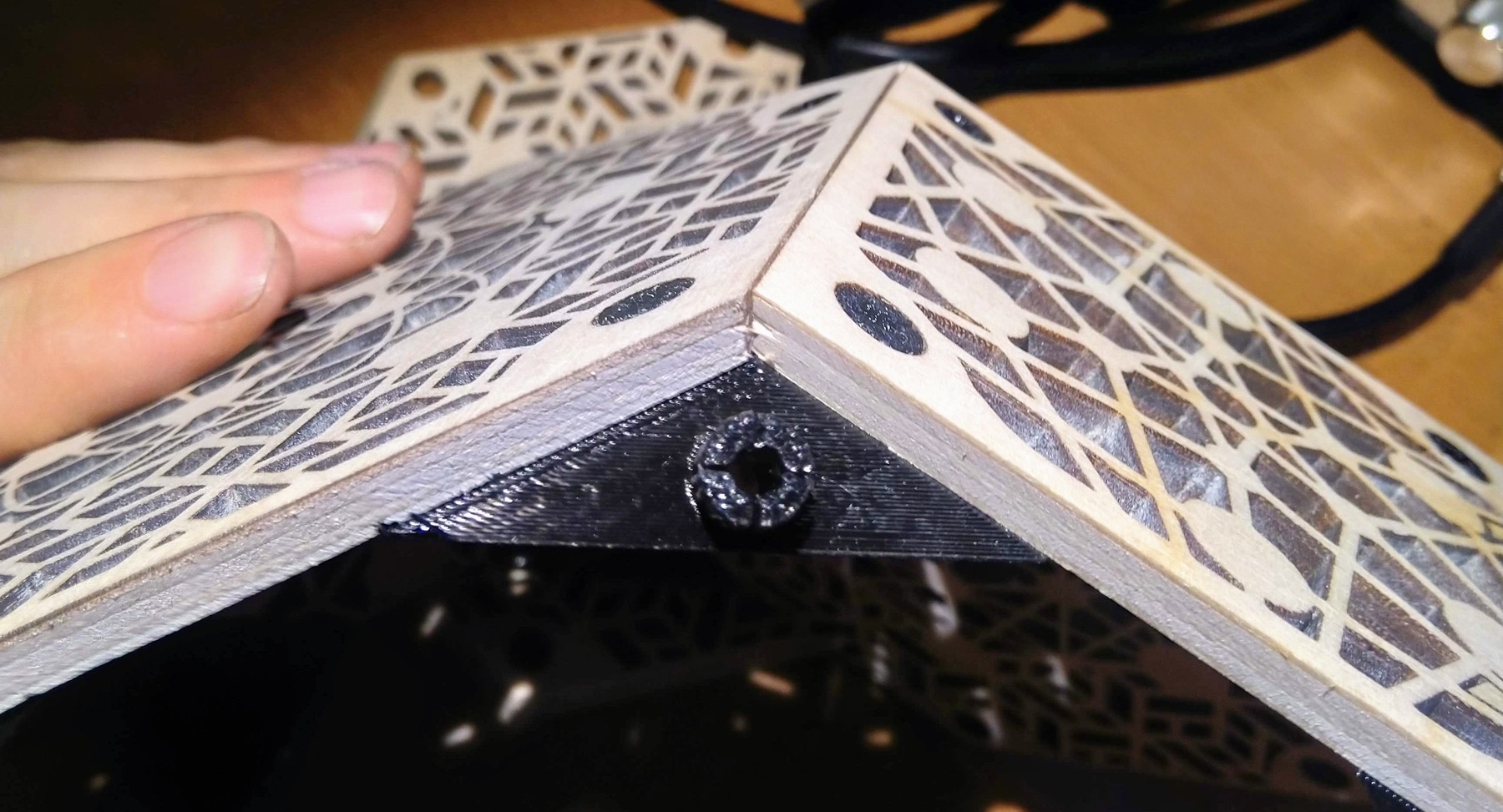
- The edges need to be chamfered at half of the angles mentioned above. The angle needs to be chosen depending on which pieces touch.
- When looking at the shape from the outside, the thicker the material, the more the mounting holes appear to be shifted towards the center of the face. This is because they are aligned with the inside edge, which is where the corner-piece will slide in.
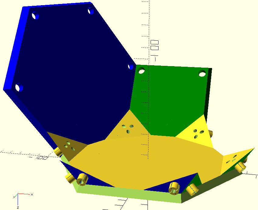
Some intersect operations later I had a good prototype.
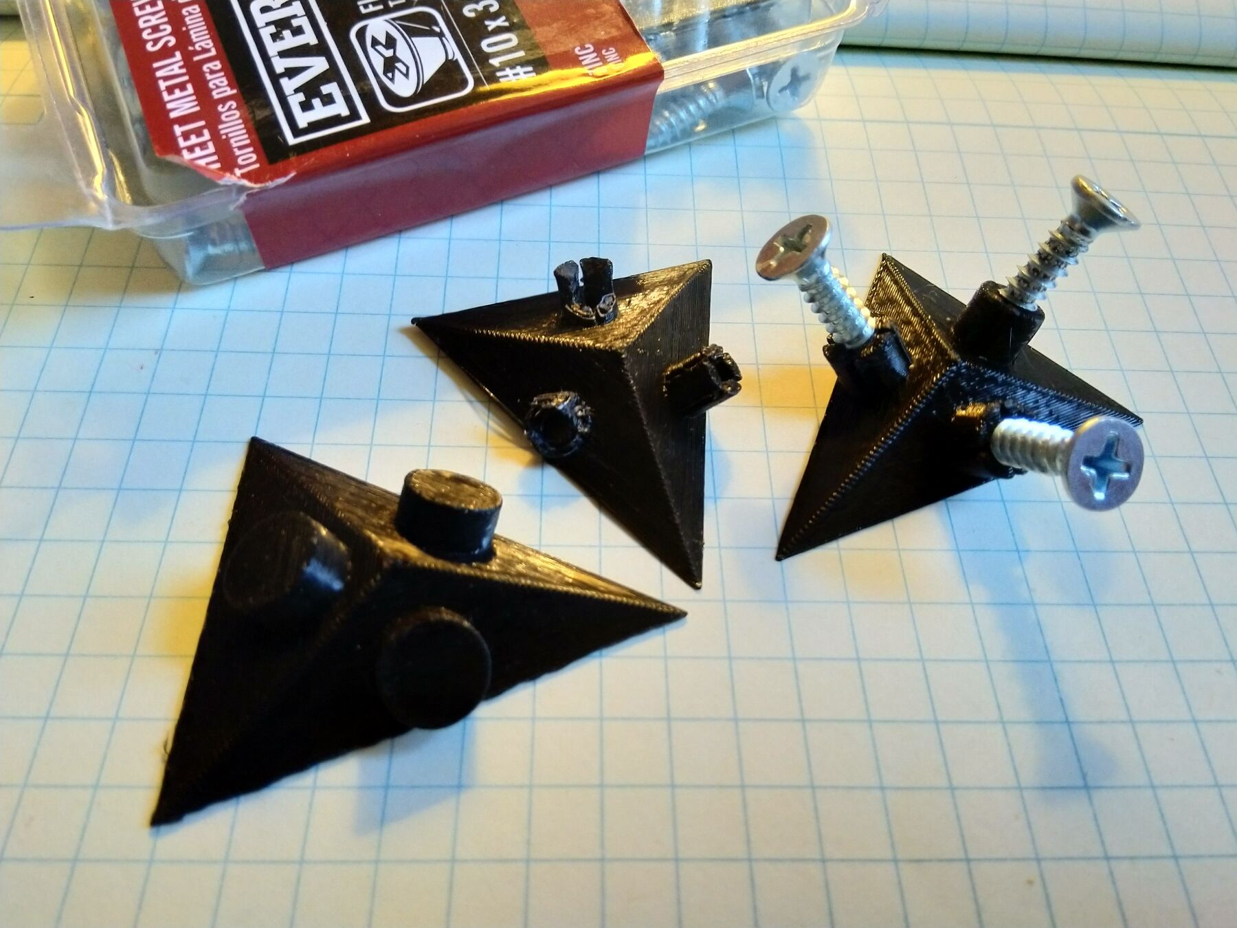
The pins are shaped to be springy for easy insertion into the mounting holes. If more stability is required, a self tapping screw can be inserted trough the middle of the pin to clamp it into place. Some things I noticed:
- The connection and the 3D printed part itself become extremely strong after inserting the screw. I could not pull it apart from a wooden plate by hand. It works similarly to a wall plug.
- It’s a single use operation. Removing the screw would usually damage the part.
- The clamping screw turned out to be overkill for this project.
It took 3 iterations on the 3D printer to come up with reasonable dimensions for the joiner piece.
Printing time is about 10 minutes for a single one or 2 hours for 12 pieces at once.
 Artwork
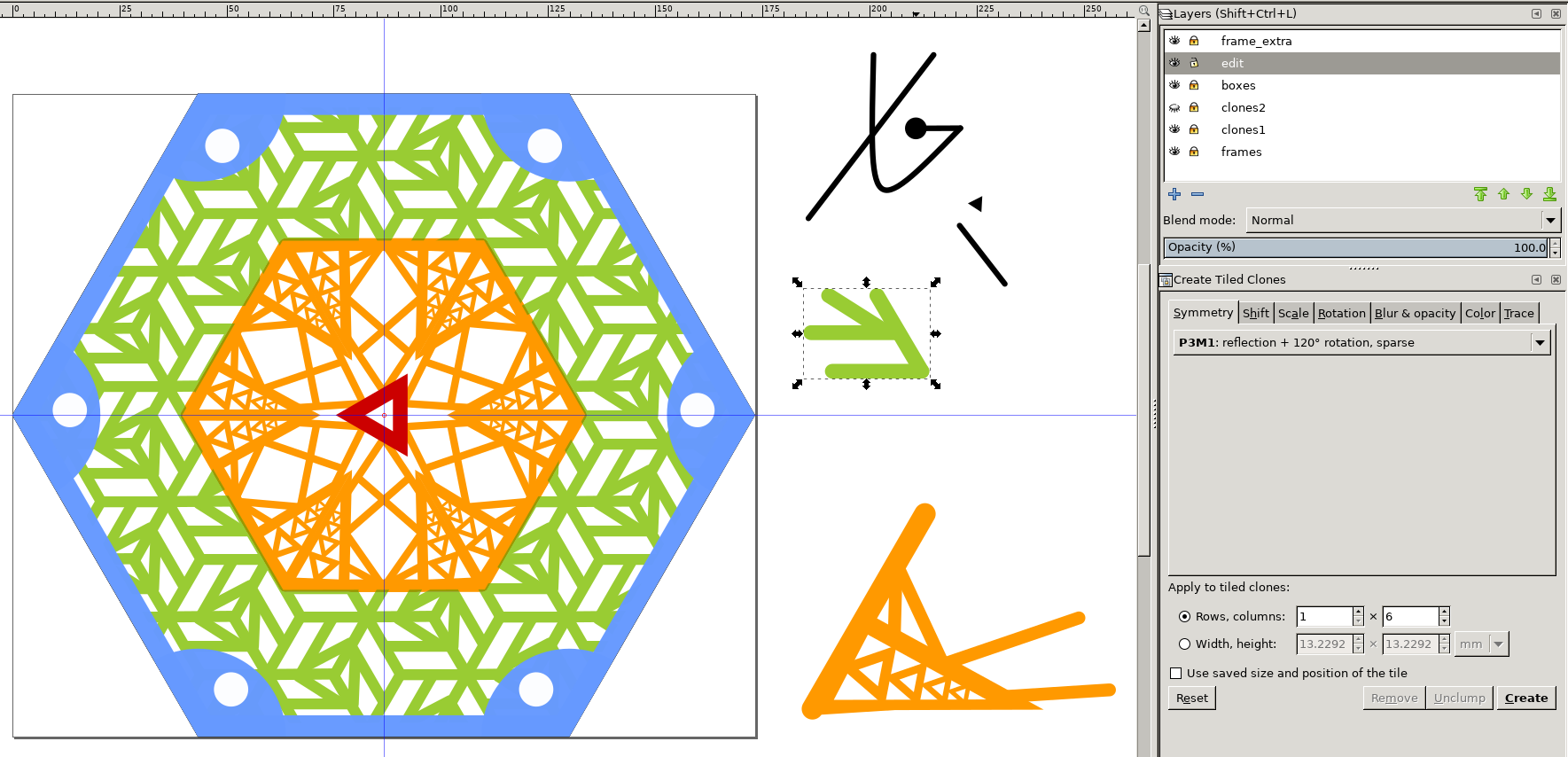
I’ve used OpenScad to export the square and hex outlines and used them in Inkscape as a template to create the artwork of correct dimension. I made heavy use of the tiled clones feature and learned some things about it:
- Use
P3,P6orP6Msymmetry. - Apply
tiled clonesto a group of objects. The group can later be entered to add more objects. - After applying
tiled clones, enter the group and move stuff around. Absolute position matters. - Use
Layersto keep the original separate from the clones for easier editing.
In Inkscape, each line has a finite thickness, which is not laser-cutter compatible. An outline of the shape is required, rendered with an infinitely thin line. I failed at exporting a clean .dxf file directly from Inkscape ![]() . Instead I came up with this horrible
. Instead I came up with this horrible ![]() workaround which gave good results:
workaround which gave good results:
- Export the black and white artwork as
.pngat extremely high resolution - Import the bitmap into a new Inkscape document
- Path –> Trace Bitmap
- Export the path as
.dxf
I recommend printing out paper templates, which are helpful to see how things fit together and to plan for the material usage. I used 1/4” plywood, leftovers from a previous project.
 Fabrication
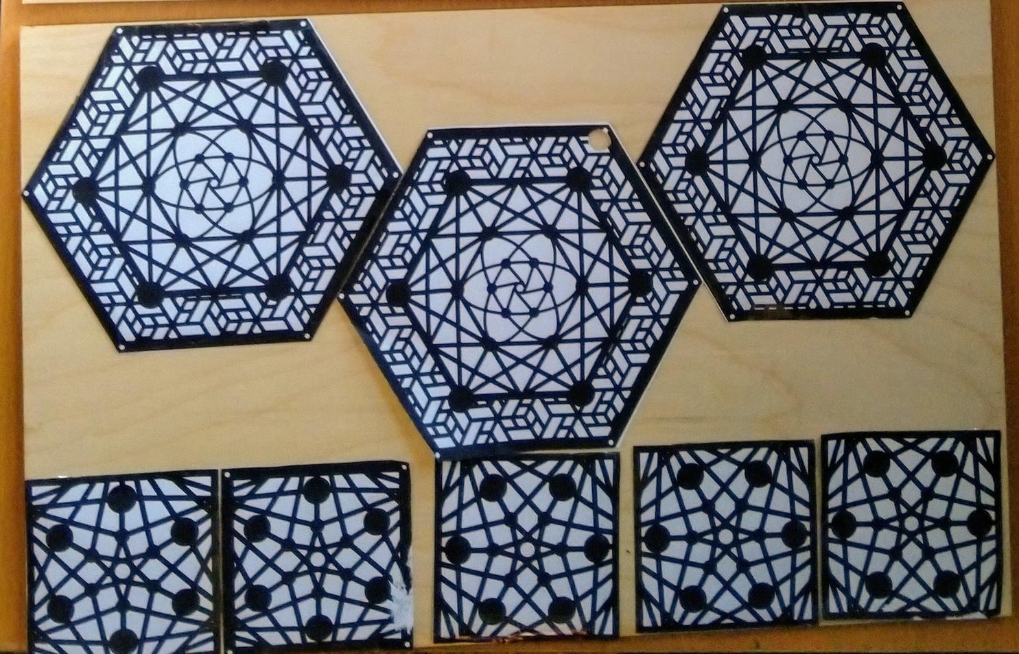
Laser cutting on the 60 W machine at Jacobs Hall went pretty smoothly. I prepared 4 different hex and 2 square designs. The hex ones took 20 - 30 min to cut each. The squares ~ 5 minutes. I had to substantially increase the cutting power above the preset as the inner layers of the plywood were of low quality and cut poorly.
To chamfer the edges I used the table-saw at the Jacobs wood-shop, tilting the blade at an angle.
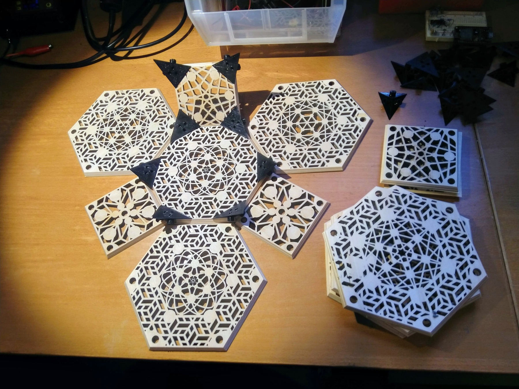
A first test-fit looks very promising ![]()
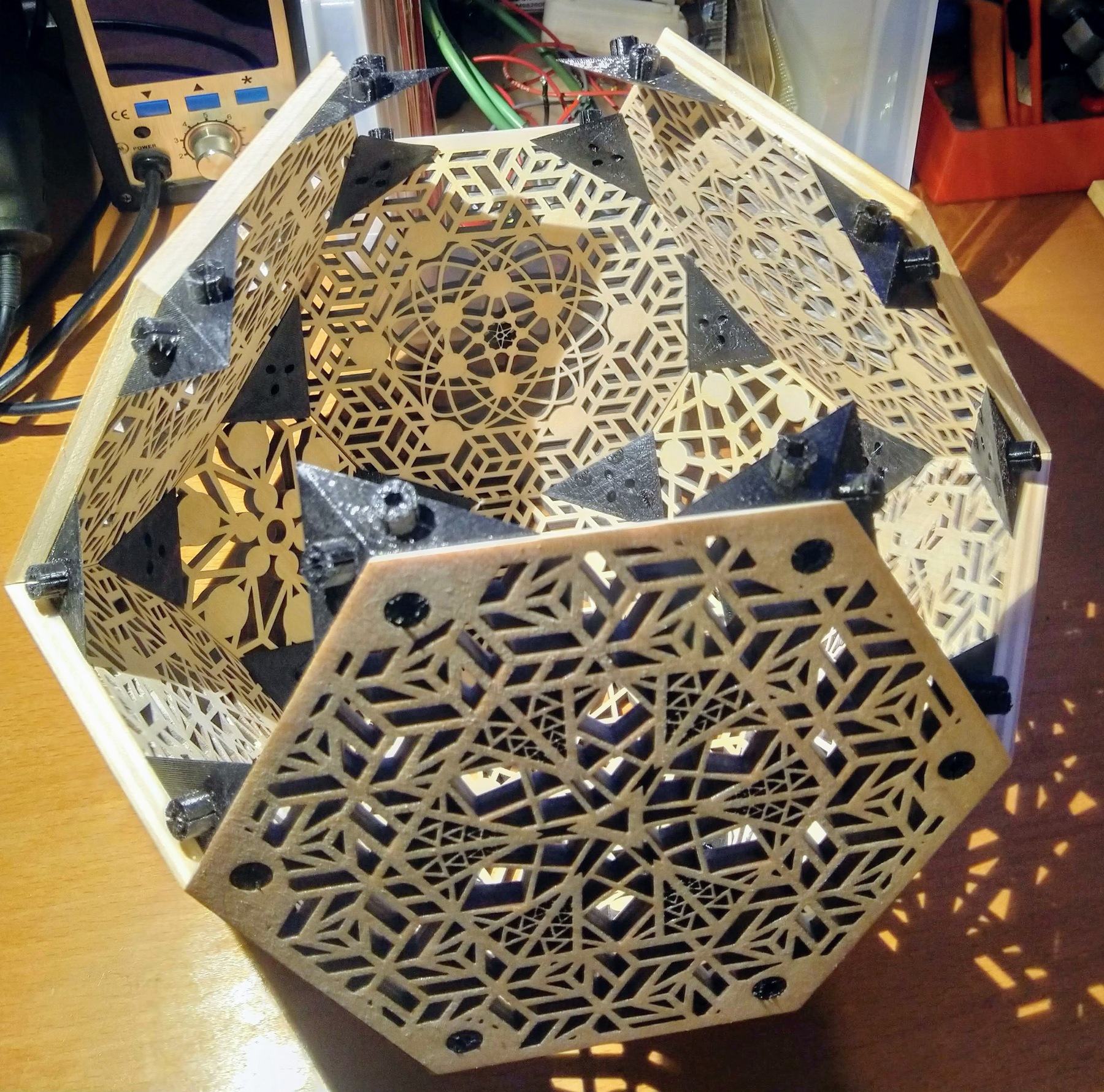
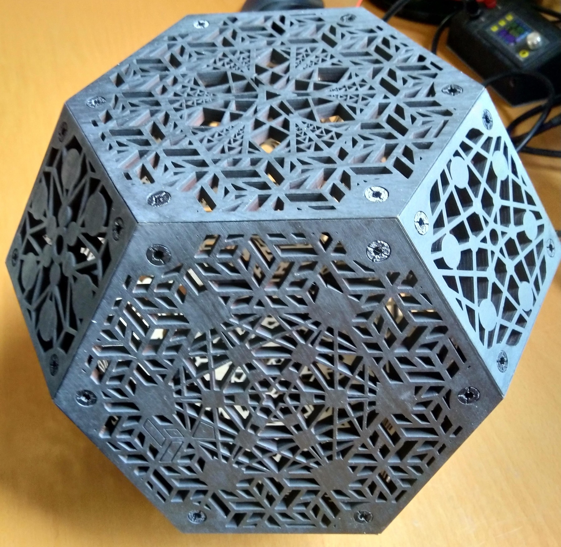
I finished each piece by sanding and applying a matte black spray paint on the outside. The inside stays natural to better reflect light.
 Illumination
My ultimate goal would be a single high power RGBW LED, mounted off-center on a slowly rotating circuit board. Power comes in through slip rings. Unfortunately I haven’t yet found a motor which is cheap, silent and can rotate slow enough. So this idea is on hold.
For now I’m sticking to a simpler solution: WS2812 LED strips formed into a spherical shape and suspended by brass wire.
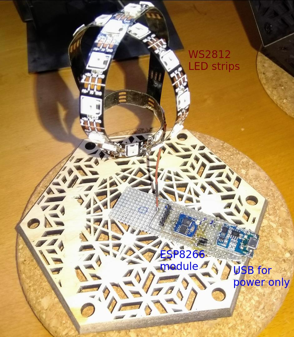
The strips are driven by an ESP8266 module. The USB connector is for power only. Programming happens through the pin header with a TTL-232R-3V3 serial cable. The 2 diodes drop the 5 V from USB to ~3.3 V which the ESP can handle.
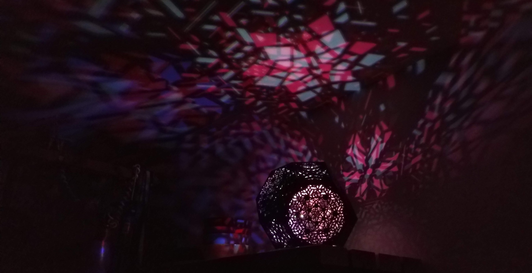
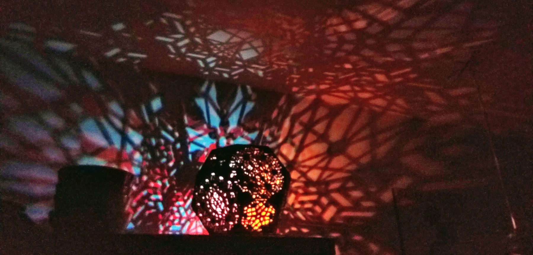
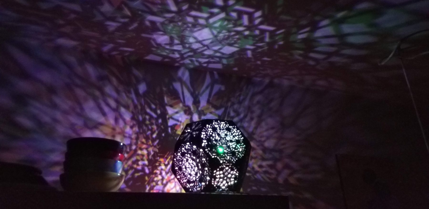
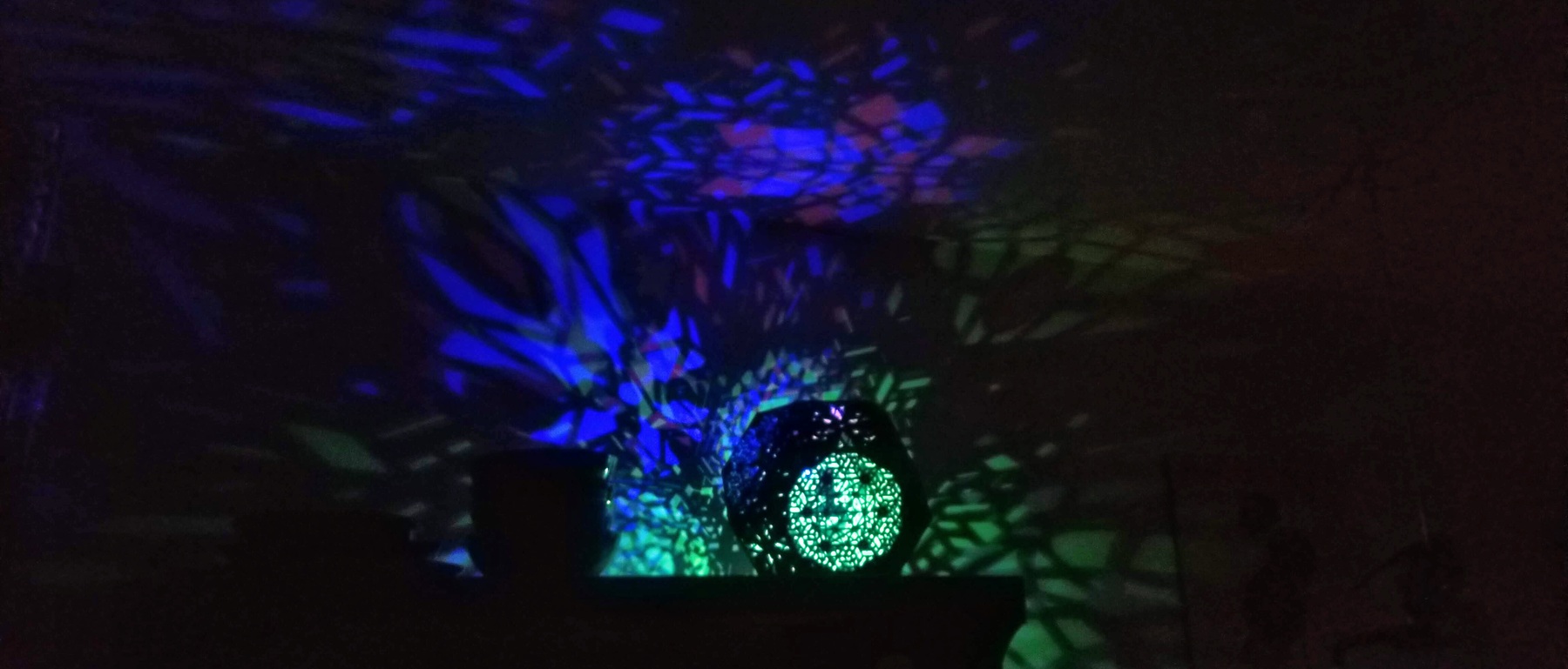
The color value, color intensity and brightness of each LED are derived from 3 independent Perlin noise sources, each doing a slow random walk. The brightness values have a negative bias, such that only a few LEDs are on at a time, making the shadows less chaotic.
 Results